

Spacecraft with minimum components to perform the test (i.e. just avionics bus, coils, and necessary mechanical components). The center of gravity is now offset, though, which would lead to an imbalanced spin. A special adapter plate was manufactured for the spindle to be directly under this configurations’ center of gravity.

The spin platform is pictured in detail here. The tube in the foreground provides compressed air which allows the spindle to spin at a low friction. On the opposite side is a photodiode encoder hooked up to an oscilloscope. That provided the reference spin period that we could use to compare with spacecraft data.
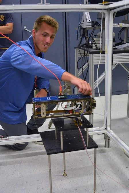
Here, Carter (’17) is about to turn ELFIN on. The square crossbeams seen here is the 3 axis Helmholtz cage.
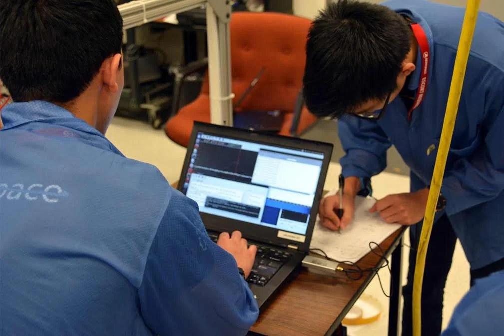
On the left, Jason (’18), who contributed much of the spin control codebase and filesystem, is seen commanding the spacecraft over the air. On the right, Kevin (’19), then-ADCS lead and designed the test, is ensuring procedures are followed and the necessary data is captured.
Spin Test
In order to resolve the pitch-angle of relativistic electron fluxes, ELFIN’s science requirements dictate a 10-30 RPM spin with control to within 2 RPM. Nominally, ELFIN maintains a spin rate of 20 RPM using its custom magnetorquers and two different spin control algorithms running on a PIC24. These algorithms were designed and simulated in MatLab/Simulink, but required a physical test on the spacecraft to gain confidence in its functionality before flight.
Devising a way to emulate a spinning spacecraft in vacuum is a challenging prospect. Not only does the test setup need to provide a low friction stable spin, but it also needs to provide a controlled magnetic field. In orbit, the entirety of our control law relies on Earth’s magnetic field: both for knowledge and for control. In space, the two algorithms, BDot and BAct, rely on Earth’s magnetic field to provide spin period and onboard phase knowledge. In addition, the magnetorquers are purposefully weak to meet magnetic cleanliness requirements — only dishing out 12-25 mN-m depending on its location in orbit given a 25,000-50,000 nT field — and thus can really only spin something up in the vacuum of space. Even on a low friction air bearing setup on the ground, it is difficult to discern the torque imparted on the spacecraft. For this test, both Tyvak Nano-Satellite System’s and Aerospace Corporation had test setups that we could try.
The following video shows the evolution of ELFIN’s spin tests over the years. Development on the bench occurred on a record player in various iterations of completion, where the speed of the record player was controlled by a Variac, allowing us to fine tune our algorithm at varying spin rates. This is key, since our microcontroller relies on digital filters and good timing to pull everything off. Keep in mind, we write all of our own software; it wasn’t just a test of the spin algorithms, but being functional in orbit usage included a working file system, optimized data collection and processing protocols, and flight-like command handling.
The first test attempt was held at Tyvak’s Irvine office in the summer of 2016. This attempt (0:18) used “air bearing islands.” These were platforms containing a few minutes worth of compressed air and three nozzles facing down creating a low friction load-bearing interface between it and a polished granite table. Unfortunately, the table was not flat enough causing the island to laterally drift rather than spin in place. This meant an external uniform magnetic field could not be applied and the spacecraft would drift to the edge of the table before any significant operational time could pass. This was clearly not the ideal setup for our purposes.

Tyvak Spin Test 2016
Although the Tyvak test was inconclusive, the team learned what operational milestones were outstanding which served as a primary factor in why the next attempt at Aerospace Corporation was successful on the first attempt. After much development, ELFIN’s control laws were ready to be tested in August 2017. This test was done using a platform on an air bearing spindle within 3 axis Helmholtz coil. The spindle was constrained laterally, but was free to rotate via the pressurized air interface. The Helmholtz coil was capable of roughly 10000 nT (20-40% of what ELFIN will see in space), which we used to adjust the localized Earth’s field to maximize spin capabilities during the test. This magnetic field, in combination with a reduced mass form factor, still isn’t enough to have ELFIN spin itself up on its own. So, the test proceeded as follows:
· Control case: Begin spinning the spacecraft at >30 RPM. Once spin reaches 30 RPM, time how long it takes to reach 5 RPM.
· This process was repeated for the various desired spin algorithms starting at exactly 30 RPM with their various configuration settings.
The purpose of this test was to ensure that the control law algorithms designed on Matlab and Simulink were implemented correctly onto the ACB and to use the data to find the optimal control law to use at different RPMs. Ideally, then, a spin up maneuver would increase the time it took from 30-5 RPM, whereas a spin down maneuver would decrease the time taken. We could then analyze the data from the spacecraft and determine if the algorithm was indeed effective or not and make the necessary optimizations.

ELFIN in foreground, test conductors in the background. Left to right. Back row: Kevin (’19) ADCS lead, Austin (’19) CDH/Ops, Jason (’18) CDH. Front row: Ethan (’17,’19) PM, Carter (’17) CDH lead